
Tweaking DSP for Stage Monitors
In the days when Digital Signal Processing first stalked the arena it was the guys at FOH that had all the fun. They would ignore their com light for long periods of time while staring intently at asymmetrical crossovers on their laptop displays. But now that DSP is affordable enough to consider using it for a dozen mixes or more the guys at the other end of the snake are beginning to experience the joys of audio in the digital domain.
There has been a lot of discussion in various forums about whether the digital approach to EQ is fast enough or user friendly enough for the monitor hot seat. There are some systems like the Ashly Protea or the BSS Varicurve (as well as a few others) that are designed to make the process of “barking” the monitors a one man job by providing a portable remote that allows you to roam the stage and EQ mixes from right in front of the wedges. Definitely a time saver. And after the monitors are tweaked you can maintain a heads up stance at the console with your eyes on the band where they belong instead of bending down, grabbing 2.5K on the bottom EQ in the rack with your precious ears a foot from the cue wedge.
But show EQ is not what I want to cover today. The real beauty of DSP in monitorland is in optimizing your wedges and side fills so that you need little or no equalization to minimize feed back. You will still have a rack full of graphics but the show will start out with all of them set flat. They will only be used for on-the-fly feedback reduction or to ”personalize” a mix. And with DSP if you have multiple wedge types in inventory a preset can be designed for each model. So let’s get on to the tweaking part.
Very few monitor cabinets are inherently “flat”. There are compromises made because of factors like box size vs. low frequency driver selection, box size vs. horn selection, low frequency driver dispersion vs. crossover frequency etc. Your favorite microphones also have frequency anomalies, especially in their off axis response. When you combine the two, things can get quite complicated. Many of these problems cannot be completely cured but with some DSP horsepower and some modern test equipment they can be minimized.
The first step is to achieve flat on-axis response from your monitors. I would highly recommend that if you don’t already own TEF, SMAART or at least an RTA you beg, borrow or steal some audio analysis equipment for this portion of the procedure. At AES a few years ago an equipment manufacturer that I have a relationship with set up a speaker, an EQ and a pink noise source in their booth. Passers-by were invited to try to equalize the pink noise by ear to achieve a flat response from the speaker. One person was spot on but most of the results were pretty scary even though the participants were all audio professionals. We need +/- 1 or 2 dB accuracy to give us a truly flat baseline to work from. Some people may have the ears to accomplish this but most of us don’t. If you are using an RTA make sure you get one that displays in increments as small as 1dB.
Measuring the low frequency response of a speaker minus the room’s acoustic contribution is a somewhat tricky proposition. A 40Hz wavelength is approximately 28 feet long. In order to measure those frequencies properly with a time windowed measurement system the window has to be long enough to contain at least one full wavelength. Unfortunately that means that it is long enough to contain room reflections that contaminate the measurement. At higher frequencies this is not a problem because the wavelengths become short enough for the windowing to provide anechoic measurements. Since real time analyzers are time blind they include room reflections at all frequencies.
There are a couple of ways to deal with this. One way is to do your testing outdoors far enough from any buildings to minimize reflected energy. My favorite approach came from one of the really smart guys in our industry named Don Keele. His approach is to place the measurement microphone about 1” from the center dome of the woofer, take a measurement, place the mic 1” from the port, take a measurement and then sum the two responses. The signal to noise ratio of the measurement is improved greatly because of the inverse square law gains from being so close to the source. A word of caution here. If the device under test has a maximum output of 120 dB at one meter, it’s output at 1” will approach 136dB. This may be enough to do bad things to your expensive measurement microphone. So start out at a fairly low volume level and work your way up. This test will give you a good idea of what is going on from 200Hz on down. The first parameter I set is a high pass filter to prevent signals that the box is not capable of reproducing from wasting power and potentially damaging components. Then correct any large EQ anomalies with parametric filters.
The microphone can be moved to the normal listening distance for this and all subsequent tests. Make sure that the distance is at least three times the longest dimension of the box under test. This puts us in the far field. I do this test with no crossover engaged for the low frequency device. If you test from 200Hz to, say, 5KHz you get a good idea of the total low frequency response curve of the box. Next, look at the upper range of the device’s response curve. There will be an obvious point where the amplitude drops off or the speaker gets into breakup modes represented on the test display by narrow notches and/or peaks. Use parametric filters to flatten the response as much as possible within the useable range of the device. Choose an upper crossover point for the woofer that filters out the nasty modes and only utilizes the relatively flat part of the speaker response.
The high frequency test is next. I prefer doing this test with no crossover engaged, however the sweep frequency must be started at a high enough frequency to avoid damaging the driver. Check the manufacturer’s recommendation for the lowest suggested crossover point and start your sweep there. If full range pink noise is being used as the test signal start with the crossover engaged to protect the driver. Using the parametric filters in your DSP of choice correct for frequency response anomalies. If the box is using a constant directivity horn you may need to use a shelving filter to increase the high frequency output above 2-3KHz. Get the response as flat as you can across the full frequency spectrum. Remember, if you leave a 3dB peak in the response and it happens to coincide with a 3dB peak in the vocal mic response it will cost you 6dB of headroom.
You should discover an overlapping frequency range where the low and high frequency devices are behaving in a fairly linear fashion. The crossover can be set anywhere within that region. As a general rule if the horn is small, set the crossover towards the high end of the overlap zone. Larger horn mouths provide pattern control down to lower frequencies so if the horn is larger, you can set the crossover point lower while maintaining good directivity from the device.
Next the levels and time alignment between the low and high frequency sections should be set. With the mic on axis and centered between the horn and woofer, do a full range sweep. Set the crossover outputs so that the average volume level is the same across the entire frequency spectrum. Then look at the frequency and phase response at the crossover frequency. Pretty ugly, eh? Using an impulse response or ETC measurement look at the arrival times for the two devices. Set the alignment delay on the DSP to eliminate the time arrival offset. Now look at the frequency and phase again. Better? You will need to do a little fine tuning to get the flattest possible phase line. If you are using an RTA this part is harder. Try inverting the polarity of the high output on the crossover. You should see a notch at the crossover frequency. Adjust the delay until the notch is at its deepest. Reset the high polarity back to normal. If the time offset is correct the notch should disappear. If your RTA has a 1/12th octave mode it will be easier to see. Some real time analyzers have a speaker timing analysis feature as well. Using asymmetrical crossover slopes can produce better (or worse) off-axis response. Experiment with this if you have time but this magazine isn’t long enough to cover all the possible permutations.
Program in some brick wall limiters just before the little red lights on the amps start to dance.
Save these settings as a preset in your DSP of choice and repeat the process for each type of monitor wedge in your inventory as well as side fills and drum monitor rigs. You can also use these settings as a basis for multiple wedge setups. But remember that when you use multiple cabinets of any sort, comb filtering will occur because of the time arrival differences. These peaks and notches are non-minimum phase. That means that they are not EQable. (Is that a word? It is now.) Sometimes it is possible to get less output with two wedges than with one because of this. But, riders being what they are, go ahead and do a preset for dual wedge setups. The crossover and time alignment settings will remain the same but you may get some summing in the low frequencies. Use the RTA to check the frequency response because a TEF sweep will be too frightening to look at. If you need a preset for absolute maximum output with a particular vocal mic try putting it on a stand exactly as if you were setting up for a show. Plug the mic into the test microphone input on the test rig. The response will be a combination of the speaker under test and the off axis response of the microphone. EQ the response to be as flat as possible. It may not sound pretty but it will get loud. At least until the singer cups the microphone sealing off the back of the cartridge and turning it into an omni. You may also want to do presets for full range response or one with a higher frequency on the low-cut filter for vocal only. Sometimes it is beneficial to attenuate the lows for an acoustic set to avoid exciting acoustic guitars or pianos. Save a preset and switch back and forth at the appropriate times.
With the current crop of DSP it is not uncommon to find configurations like 4-in 8-out which work perfectly for either four two-way mixes or two three-way side fills and a cue wedge. Look for routing flexibility and the ability to store lots of presets. But most of all listen to the units. Audio quality varies as much with digital equipment as with analog. It’s too easy to buy this type of device based on a laundry list of features and functions when the most important thing is great sound. Just think of how impressed that visiting monitor mixer will be when you tell him that the monitors are all wrung out and the graphics are still flat!
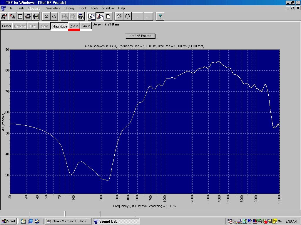
Highs Pre EQ
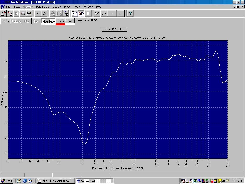
Highs Post EQ

Final Result
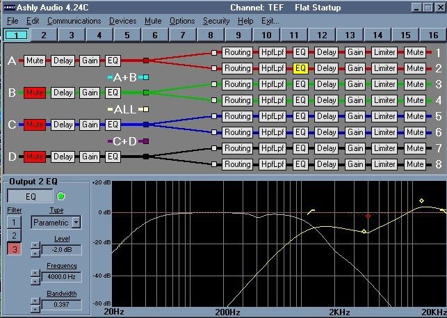
DSP Results